STM32 DSP & Embedded Labs
A run of bare-metal STM32L4 firmware: synthesizing waveforms out to the DAC, reading the on-chip temperature and voltage-reference sensors through the ADC, pulling data off an I²C gyroscope, and finally running it all as concurrent FreeRTOS tasks. Written in C on the HAL, with CMSIS-DSP and ARM assembly.
The thread running through all of it
Four labs, one Cortex-M4F, and a steady climb up the embedded stack: from pushing samples straight at a DAC, to reading real sensors through the ADC, to talking to an external chip over I²C, to scheduling all of it concurrently under a real-time OS. Everything is bare-metal C on ST's HAL, dropping into ARM assembly and CMSIS-DSP where the signal-processing work wanted it.
1 · Synthesizing waveforms to the DAC
The first job was turning the MCU into a function generator: compute sample values in firmware and stream them out of the on-chip DAC to make saw, triangle and sine waves at a chosen frequency. The generators are just a mapping from an elapsed-time counter to an 8-bit output level — here are two of mine:
// Software waveform synthesis — sample values streamed to the STM32 DAC.
// Each generator maps an elapsed-time counter to an 8-bit output level.

uint8_t saw(float frequency, int iter) {
    int period = (1 / frequency) * 1000;      // period in ms
    int mod    = fmod(iter, period);
    return (uint8_t)(255 * mod / period);     // ramp 0 → 255
}

uint8_t triangle(float frequency, int iter) {
    int   period = (1 / frequency) * 1000;
    float mod    = fmod(iter, period) / period;
    if (mod < 0.5)                            // rising half
        return (uint8_t)(2 * 255 * mod);
    return (uint8_t)(255 - 2 * 255 * (mod - 0.5));  // falling half
}2 · Reading the on-chip sensors through the ADC
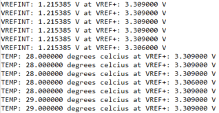
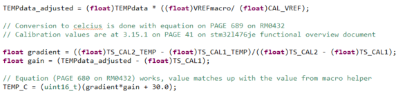
Every STM32 hides two useful sensors on internal ADC channels: a temperature sensor and the internal voltage reference (VREFINT). Reading them well is a small lesson in real measurement — the raw ADC count means nothing until it's referred back to a known voltage using the factory calibration values baked into the chip.
3 · Talking to an I²C gyroscope
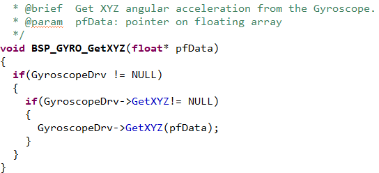
Next, an external sensor: reading angular-rate data off the board's gyroscope over I²C. This is the everyday reality of embedded work — bring up a two-wire bus, read the device's WHO_AM_I to prove the link, configure control registers, then pull the multi-byte axis readings and convert raw counts to physical units.
4 · Running it all under FreeRTOS
The final lab moved from one super-loop to a proper real-time OS: separate FreeRTOS tasks for the push-button, the sensor reads and the UART output, coordinated by priorities and inter-task signalling. It's the jump from "do everything in order, forever" to "several things happening concurrently, each meeting its own timing" — the model real embedded products actually run on.
What I took away from it
- Bare-metal peripheral bring-up across DAC, ADC, I²C and UART on the HAL, dropping to ARM assembly and CMSIS-DSP for the signal-processing paths.
- Real measurement discipline — referring ADC counts back to a calibrated reference before trusting a number.
- Timer-driven DMA for precise, CPU-independent sample streaming.
- Structuring firmware as concurrent FreeRTOS tasks with priorities, rather than one monolithic loop.